Building and Testing Quadrotor Drone
This project covers the complete end-to-end process of building and flight-testing a quadrotor drone from scratch. Starting from selecting the right hardware components, through mechanical assembly, flight-controller firmware configuration, remote controller binding, GPS setup, full sensor calibration in QGroundControl (QGC), and finally a successful outdoor test flight. The workflow follows industry-standard practices used in ArduPilot / PX4 based UAV development.
The following hardware was selected for building a stable and responsive quadrotor capable of GPS-assisted flight:
| Component | Specification / Model | Purpose |
|---|---|---|
| Frame | F450 / S500 Quadrotor Frame | Structural chassis, 450 mm wheelbase |
| Flight Controller | Pixhawk 4 / Cube Orange | Autopilot with IMU, barometer, MAVLink |
| Motors | 2212 920KV Brushless Motors (×4) | Propulsion — CW & CCW pairs |
| ESCs | 30A Electronic Speed Controllers (×4) | Motor speed control via PWM |
| Propellers | 1045 (10 inch, 4.5 pitch) — 2 CW + 2 CCW | Thrust generation |
| Battery | 3S / 4S 5200 mAh LiPo | Power supply |
| Power Distribution Board | PDB with BEC | Distribute power to ESCs and FC |
| GPS Module | Neo-M8N / Here3 GPS + Compass | Position hold, RTL, waypoint missions |
| RC Receiver | FrSky X8R / FlySky FS-iA10B | Receive RC commands from transmitter |
| RC Transmitter | FrSky Taranis X9D / FlySky FS-i6X (10ch) | Manual pilot control |
| Telemetry Radio | SiK 915 MHz / 433 MHz (×2) | GCS ↔ drone MAVLink link |
| Companion Computer (Optional) | Raspberry Pi 4 | ROS2 / onboard processing |
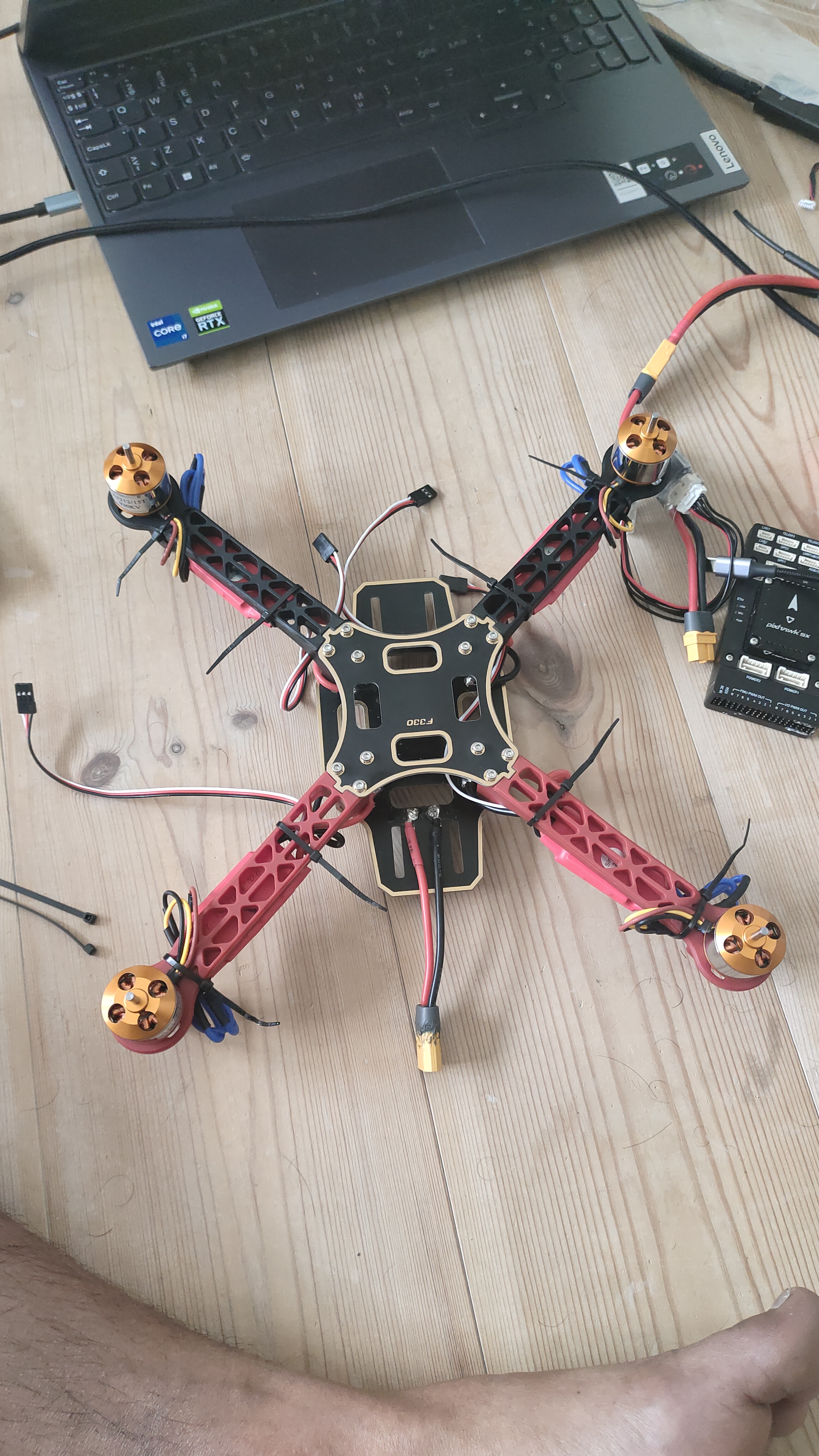
Assembly was performed in a systematic order to ensure clean wiring and structural rigidity:
2.1 — Frame Assembly
- Mount the four arms onto the central frame plate using M3 bolts. Identify motor positions: two front (CW), two rear (CCW).
- Attach the landing gear legs to the bottom plate for ground clearance.
- Route motor wires through the arm channels to keep wiring clean and protected.
2.2 — Motor & ESC Mounting
- Bolt each 2212 920KV brushless motor to the tip of each arm using M3 screws.
- Mount one 30A ESC on each arm using zip ties or velcro. Keep ESCs away from motor heat.
- Connect motor phase wires (3-wire) to ESC output. Note: motor direction will be verified and corrected in QGC.
- Connect ESC power leads (red & black) to the Power Distribution Board (PDB).
2.3 — Power Distribution Board (PDB)
- Solder all four ESC power pairs to the PDB pads. Observe polarity — red to +, black to −.
- Solder the main battery XT60 connector to the PDB input.
- Take a regulated 5V BEC output from the PDB to power the Pixhawk.
2.4 — Flight Controller Mounting
- Mount Pixhawk 4 in the center of the frame using anti-vibration foam pads. Arrow on Pixhawk must face the drone's front.
- Connect ESC signal wires (PWM) to Pixhawk's MAIN OUT ports: Motor 1 → MAIN 1, Motor 2 → MAIN 2, Motor 3 → MAIN 3, Motor 4 → MAIN 4.
- Connect the 5V BEC power to the Pixhawk power module port.
2.5 — Propeller Mounting
- Attach CW propellers (standard thread) on motors 1 & 3 (front-right and rear-left).
- Attach CCW propellers (reverse thread) on motors 2 & 4 (front-left and rear-right).
- Important: Do NOT mount propellers until all ESC direction checks are completed safely in QGC.
QGroundControl (QGC) is the ground control station used to configure the Pixhawk, verify actuators, and monitor telemetry. Connect the Pixhawk to the laptop via USB and open QGC.
3.1 — Firmware Flash
- In QGC: Vehicle Setup → Firmware. Select ArduPilot or PX4 and flash the latest stable release for quadrotor.
- After flashing, QGC will reboot the Pixhawk and auto-detect the frame type.
3.2 — Airframe Selection
- Go to Vehicle Setup → Airframe.
- Select Quadrotor X configuration (X-frame layout). Apply & restart.
3.3 — Motor Test & Direction Verification
- Go to Vehicle Setup → Motors (with props OFF and battery connected).
- Slide each motor slider individually and verify each physical motor spins correctly.
- If a motor spins in the wrong direction, swap any two of its three ESC-to-motor phase wires to reverse it.
- Verify the standard ArduPilot quadrotor X spin pattern:
- Motor 1 (Front-Right) — CCW
- Motor 2 (Rear-Left) — CCW
- Motor 3 (Front-Left) — CW
- Motor 4 (Rear-Right) — CW
3.4 — ESC Calibration
- In QGC: Vehicle Setup → Power → ESC Calibration.
- Follow the wizard: disconnect battery, click calibrate, reconnect battery when prompted. Listen for ESC tones confirming min/max throttle registration.
- This ensures all ESCs respond identically to the same throttle input.
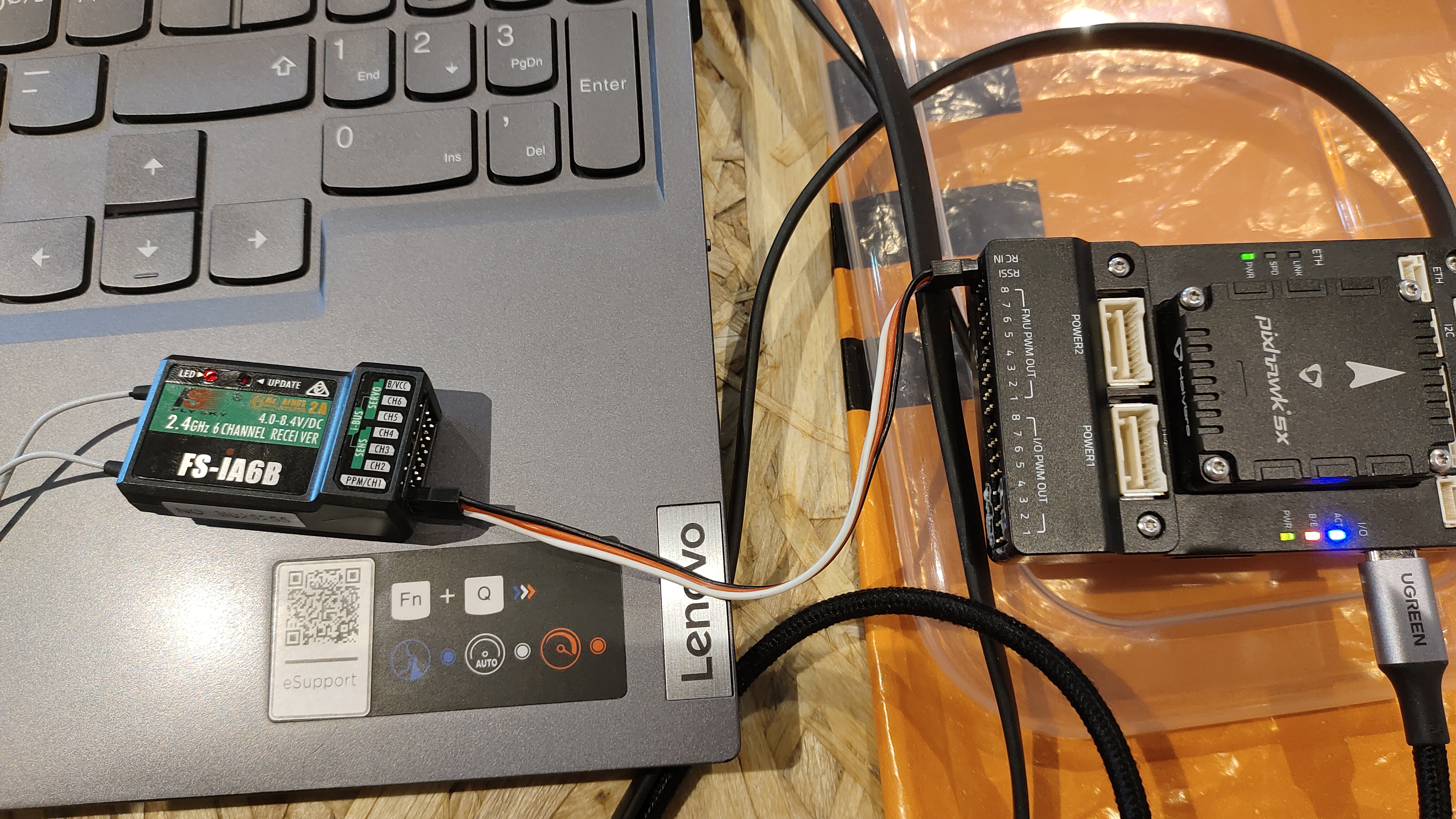
4.1 — Bind Receiver to Transmitter
- For FrSky: Hold the bind button on X8R receiver, power on, then enter bind mode on Taranis. Release when solid LED appears.
- For FlySky: Hold BIND on FS-iA10B, power the drone, then enter bind on FS-i6X transmitter.
- Confirm solid LED on receiver indicating successful bind.
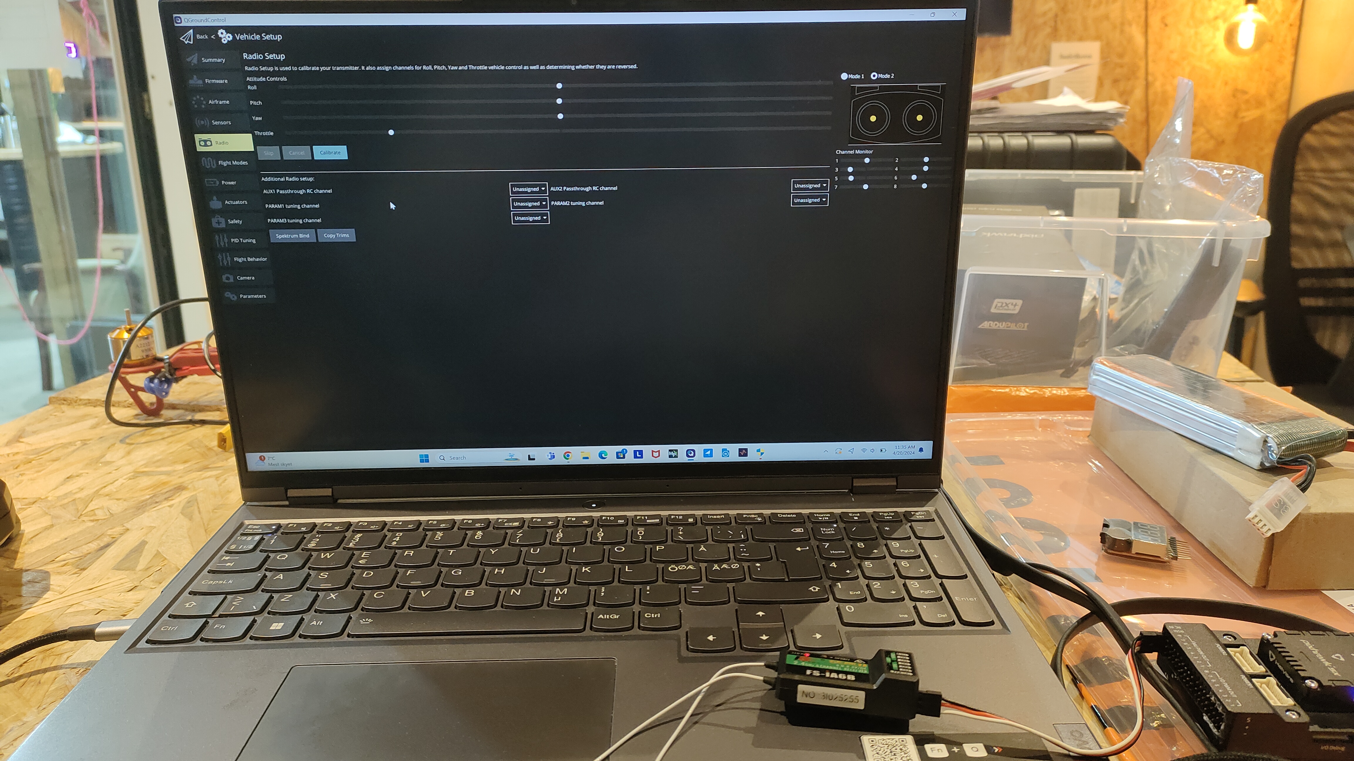
4.2 — RC Calibration in QGC
- Connect receiver signal to Pixhawk RC IN port (SBUS or PPM).
- Go to Vehicle Setup → Radio in QGC. Click Calibrate.
- Move all sticks and switches through their full range when prompted. QGC captures min, max, and trim values.
- Verify channel mapping: Ch1 = Roll, Ch2 = Pitch, Ch3 = Throttle, Ch4 = Yaw, Ch5 = Flight Mode switch.
4.3 — Flight Mode Configuration
- Go to Vehicle Setup → Flight Modes.
- Assign at least three modes to the 3-position switch on Ch5:
- Stabilize — manual with self-levelling
- AltHold — barometer-assisted altitude hold
- Loiter — GPS position and altitude hold
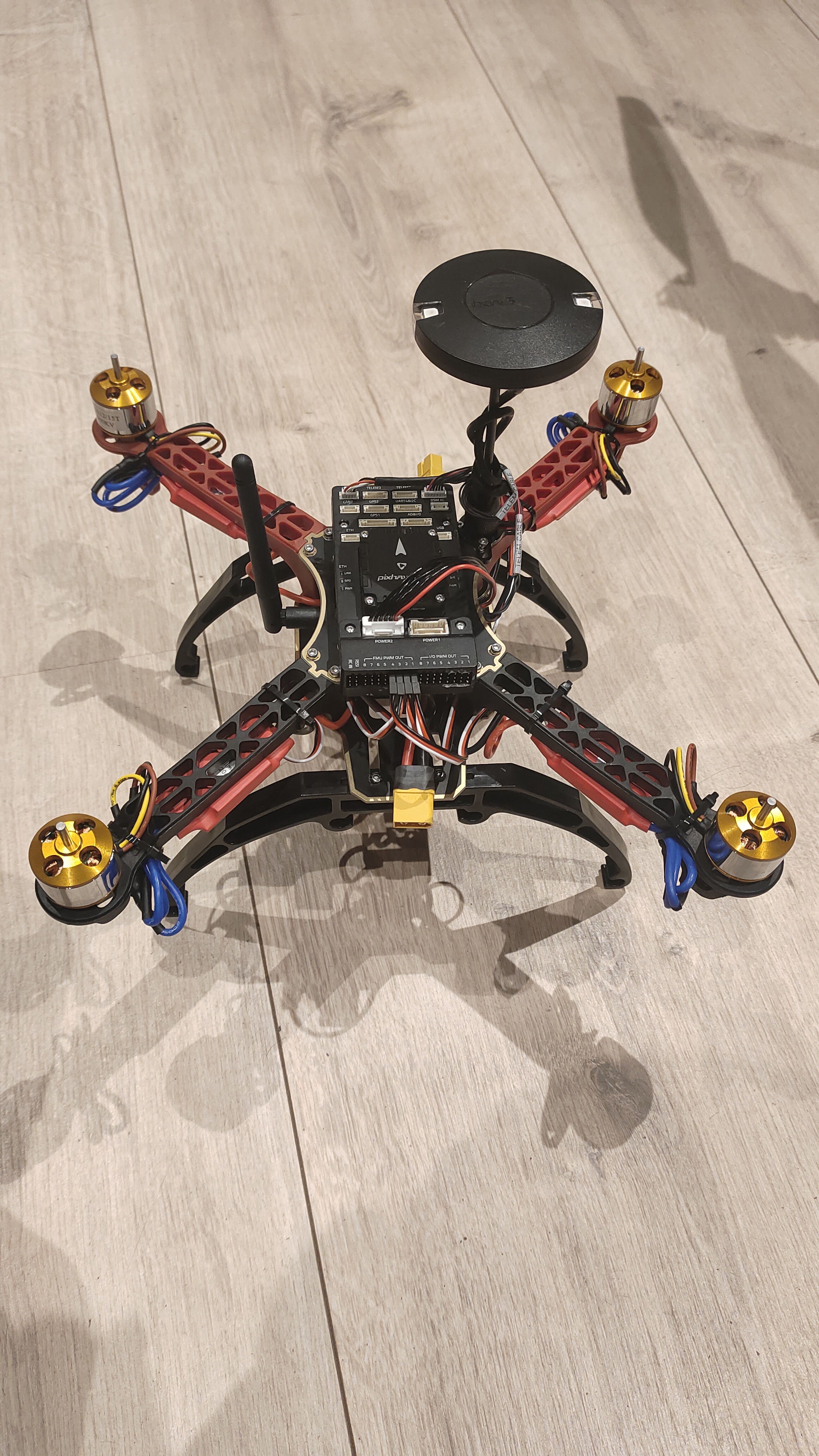
5.1 — Physical Mounting
- Mount the GPS/Compass module on a raised mast at the top-rear of the drone, away from ESCs, motors, and power wires to reduce magnetic interference.
- Ensure the GPS arrow points forward (aligned with Pixhawk's forward arrow).
5.2 — Wiring
- Connect GPS UART cable to Pixhawk's GPS1 port.
- Connect the compass I2C cable to Pixhawk's I2C port (or it may be combined in a single cable for modules like Here3).
5.3 — QGC GPS Verification
- Go outdoors with a clear sky view. Check QGC status bar for GPS fix icon.
- Wait for 3D GPS lock — typically requires ≥6 satellites and HDOP < 2.0.
- The home position is automatically set on first GPS lock after arming.
All calibrations are performed in QGC under Vehicle Setup. Perform them indoors away from metal structures.
6.1 — Accelerometer Calibration
- Go to Sensors → Accelerometer. Click Calibrate.
- Place the drone flat on each of its 6 faces (level, nose down, tail down, left side, right side, upside down) when prompted by QGC. Click OK between each.
- This corrects IMU offset and ensures the drone knows its true horizontal level.
6.2 — Compass Calibration
- Go to Sensors → Compass. Click Calibrate.
- Rotate the drone slowly through all orientations — roll, pitch, and yaw — until all compass spheres fill up in QGC.
- Perform outdoors or in an open space, away from iron structures and electronics. Remove any magnetic tools nearby.
6.3 — Level Horizon
- Place the drone on a flat, level surface.
- Go to Sensors → Level Horizon. Click Calibrate to set the neutral pitch/roll reference.
6.4 — Radio & Battery Configuration
- Set battery cell count and capacity in Power section. Enable low-battery failsafe (e.g., RTL below 20%).
- Enable RC loss failsafe to trigger RTL if signal is lost for >1 second.
Before the first flight, perform a thorough pre-flight checklist:
7.1 — Pre-Flight Checklist
- ✅ All calibrations passed (no yellow/red warnings in QGC).
- ✅ Props securely tightened — CW and CCW correctly placed.
- ✅ Battery fully charged and XT60 connector firmly plugged in.
- ✅ RC transmitter powered and linked — all sticks respond in QGC radio screen.
- ✅ GPS lock acquired (≥6 sats, HDOP < 2.0) shown in QGC HUD.
- ✅ Flight mode switch set to Stabilize for first flight.
- ✅ Test area is open, flat, with no people or obstacles within 20 m.
7.2 — Arming & Hover Test
- Arm the drone: hold throttle-down and yaw-right for 3 seconds on the transmitter. Motors will start spinning slowly.
- Slowly increase throttle until the drone lifts off (~50–60% throttle for hover).
- Hover at ~1 m altitude for 30 seconds. Observe stability — drone should hold roughly level without large corrections needed.
- Test roll, pitch, and yaw inputs gently to verify control response.
- Disarm: hold throttle-down and yaw-left for 3 seconds after landing.
7.3 — AltHold & Loiter Test
- Switch to AltHold mode. Release throttle stick to center — drone should maintain altitude automatically using barometer.
- Switch to Loiter mode (GPS required). Drone should hold its XY position against wind. Release all sticks and observe.
- Test Return-to-Launch (RTL): trigger via flight mode switch. Drone should ascend to RTL altitude, fly back to home position, and auto-land.
- Successfully built and assembled a stable quadrotor from individual components.
- All motors verified with correct spin direction; ESCs calibrated for uniform response.
- Full sensor suite calibrated via QGroundControl — IMU, compass, RC, and battery.
- GPS lock acquired reliably with 3D fix; position hold (Loiter) verified outdoors.
- Test flight completed: stable hover, responsive manual control, and autonomous RTL confirmed.
Motor test and initial hover validation — April 2024
- Pixhawk 4 (ArduCopter firmware): Core autopilot — handles sensor fusion (IMU + barometer + GPS + compass), motor mixing, PID control, and MAVLink telemetry.
- ESC + Brushless Motors: Each ESC converts PWM commands from Pixhawk into motor RPM for all four propulsion units.
- GPS/Compass Module: Provides absolute position (lat/lon/alt) and heading for Loiter, RTL, and waypoint missions.
- FrSky / FlySky RC System: Sends pilot commands on up to 10 channels via SBUS/PPM to Pixhawk RC input.
- Telemetry Radio: MAVLink bidirectional link between Pixhawk and QGC on a ground laptop for real-time monitoring.
- QGroundControl (QGC): Ground control station for firmware flashing, parameter tuning, calibration, mission planning, and live HUD.
This build establishes a strong platform for further autonomous capability development:
- ROS2 + MAVROS Integration: Run high-level autonomy nodes on a companion Raspberry Pi, bridging ROS2 topics to Pixhawk via MAVROS.
- Autonomous Waypoint Missions: Plan and execute multi-waypoint GPS missions via QGC Mission Editor or custom ROS2 mission nodes.
- Vision-Based Navigation: Integrate a downward-facing camera with optical flow for GPS-denied indoor position hold.
- Object Detection Payload: Mount a Jetson Nano with a camera for real-time YOLO-based aerial surveillance and inspection tasks.
Conclusion
By following a structured build process — from component selection and mechanical assembly through ESC wiring, QGC firmware and motor configuration, RC binding, GPS integration, and full sensor calibration — the quadrotor was successfully assembled and flight-tested. The drone demonstrated stable hover, responsive manual control, and reliable GPS-assisted autonomous modes including Loiter and RTL. This project provides a solid, extensible hardware foundation ready for advanced autonomy research using ROS2, computer vision, and custom mission planning.