SITL-Based Simulation and Gazebo Visualization with ArduPilot Integration
Click On the Video to View full Video on YouTube
Abstract
This project presents a comprehensive three-stage approach to simulating and testing quadrotor (drone) behavior using the ArduPilot autopilot software stack. The first stage utilizes the Software-In-The-Loop (SITL) framework to emulate quadrotor dynamics without physical hardware. The second stage enhances realism by integrating SITL with the Gazebo simulator, allowing for 3D visualization and interaction using the Iris model. Finally, the third stage connects the simulation environment with ROS (Robot Operating System) via MAVROS, enabling ROS-based control and sensor integration. This simulation platform supports flight modes like Circle, RTL, AltHold, and Auto Mission Planning, offering a safe and extensible testbed for UAV development.
Introduction
Autonomous aerial robots like quadrotors are widely used for inspection, mapping, and surveillance. Real-world testing is risky and expensive, especially during early development. SITL allows developers to simulate UAV behavior using the actual ArduPilot firmware stack in software.
This project includes three key phases:
- SITL-Based Simulation with MAVProxy GCS: Emulate UAV control and dynamics using terminal-based interface.
- SITL + Gazebo Integration: Add realistic 3D environment for visualizing drone flight using the Iris model.
- SITL + Gazebo + MAVROS Interface: Integrate with ROS for higher-level autonomy, path planning, and sensor interfacing.
System Overview
- ArduPilot Stack: Open-source autopilot framework with ArduCopter firmware
- SITL: Simulates flight controller behavior in software
- MAVProxy GCS: CLI for mission planning and telemetry
- Flight Modes: Circle, RTL, Auto, GeoFence, AltHold
- Gazebo Simulator: 3D simulation for dynamic behavior
- Quadrotor Model: Iris (predefined in Gazebo)
- Middleware: MAVLink protocol for communication
Part 1: SITL-Based Simulation with ArduPilot
The first phase of the project focuses on simulating UAV behavior using the SITL framework. SITL allows execution of the ArduCopter firmware in a fully virtual environment.
✅ Setup Highlights:
- ArduPilot stack is executed on a virtual ArduCopter.
- Internal flight simulator handles dynamics without hardware.
- MAVProxy GCS provides a command-line interface for sending control commands and drawing mission plans.
- Internally linked components: ArduPilot ⇄ MAVProxy ⇄ Map & Console (via UDP).
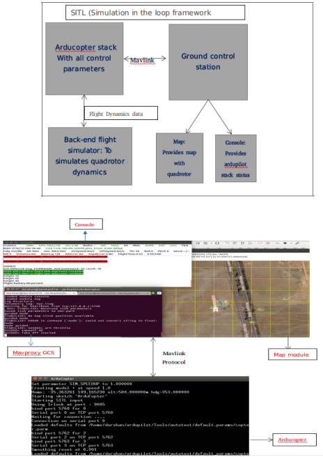
Figure: SITL-Based Simulation with ArduPilot Architecture
Flight Modes and Commands
Circle Mode
In this mode, the quadrotor spins in a circular path using throttle and radius parameters.
      arm throttle (activate motors)
      takeoff 50 (take-off the model upto 50cm height)
      rc 3 1500 (set the motor speed to 1500rpm)
      param set circle_radius 2000 (set the radius to 2000cm)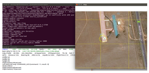
Figure: GeoFence Mode Setup with Boundary Constraints
Mission Plan (Auto Mode)
In Auto Mode, the user defines a series of waypoints on the MAVProxy Map. The quadrotor autonomously follows the mission path after takeoff.
      arm throttle          (activate motors)
      takeoff 20            (take-off the model up to 20cm height)
      mode auto             (switch to Auto mode to follow mission)
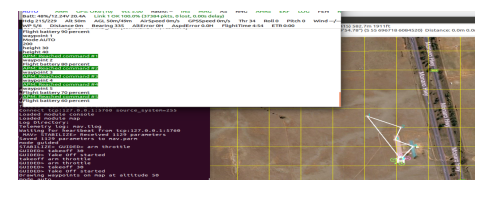
Figure: Mission Planning using MAVProxy Map
GeoFence Mode
GeoFence Mode defines virtual boundaries in the airspace. The UAV stays within these boundaries and returns or lands if it tries to breach them.
      arm throttle          (activate motors)
      takeoff 20            (take-off the model up to 20cm height)
      mode auto             (switch to Auto mode with GeoFence active)
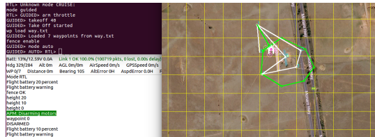
Figure: GeoFence Mode Setup with Boundary Constraints
Part 2: Integrating SITL with Gazebo for 3D Visualization
Enhancing the simulation by integrating Gazebo with SITL for real-time visual feedback using the Iris quadrotor model.
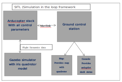
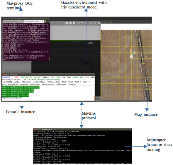
Figure: SITL + Gazebo Architecture Overview
Mission Planning
To execute an autonomous mission, users can define waypoints directly on the MAVProxy Map:
- Right-click on the map and select “Draw Mission”.
- Click to add multiple pose points (waypoints).
- Left-click to finish drawing the mission plan.
Once the mission path is drawn, execute the following commands in the MAVProxy terminal to begin the autonomous flight:
arm throttle          (activate motors)
takeoff 20            (take-off the model up to 20cm height)
mode auto             (set to Auto mode to start mission execution)
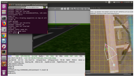
Figure: Mission Planning using MAVProxy Map Interface
Part 3: Interfacing SITL + Gazebo with MAVROS
Until this point, the quadrotor simulation using SITL was controlled via the MAVProxy GCS terminal. The next phase of the project introduces integration with the Robot Operating System (ROS) to enable access to high-level robotics tools such as navigation stacks, perception pipelines, and planning algorithms.
MAVROS acts as a bridge between the MAVLink protocol (used by ArduPilot) and the ROS ecosystem. It translates MAVLink messages into ROS topics, enabling bi-directional communication between ArduPilot and ROS nodes. Additionally, MAVROS serves as a proxy interface for GCS commands and telemetry.
An open-source package named ardupilot_gazebo (available on ROS wiki) provides the base for SITL-Gazebo-MAVROS integration. For this project:
- The
irisquadrotor model was extended by adding a camera and its Gazebo plugin. - MAVROS was configured to receive and publish flight data from the ArduPilot SITL environment.
- The system allows ROS nodes to monitor quadrotor state, issue commands, and interact with sensor outputs like camera feeds.
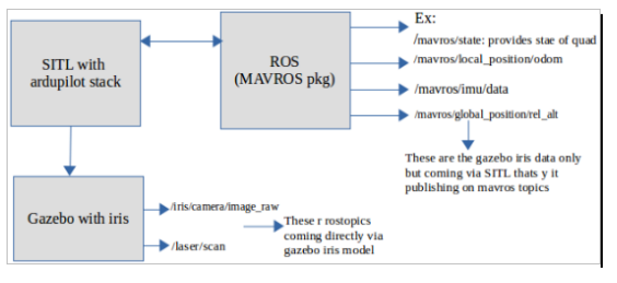
Figure: SITL + Gazebo Integrated with MAVROS for ROS Communication
Conclusion
This three-stage simulation project successfully demonstrates a scalable and modular approach to autonomous quadrotor testing using the ArduPilot ecosystem. The SITL and MAVProxy setup enabled safe emulation of flight behavior and mode switching without hardware. The Gazebo integration added rich 3D visualization for real-time observation and validation of UAV dynamics. Finally, the SITL + Gazebo + MAVROS interface bridged the system with the ROS ecosystem, enabling access to advanced autonomy tools, sensor integration, and future navigation algorithms. Together, this layered architecture provides a powerful testbed for developing, debugging, and validating UAV applications prior to real-world deployment.